Tuesday, April 23, 2019
Thursday, February 9, 2017
Fabricating the Elevator!
Hello .. it has been a long time since I have updated this blog.
After joining the Facebook community, I started posting the PIK repairs there. So, it's time for me to update the blog.
 As mentioned in earlier posts, the elevator was totally destroyed and not repairable. I fortunately had the elevator from Roberts PIK-20B to use as a pattern for a mold.
 After making the mold, I found that the top and bottom of the elevator was symmetrical, so a making a two sided mold was not necessary.

At the time I started the fabrication of the skins, I was unable to find any drawings from the PIK website in Finland. I tried contacting them but after months of waiting, I started looking at other options. The only reference I had was the repair manual and the elevator from Robert.
The manual had the glass layup as a single ply of 92110 and 92125 on the 0 axis (running the length of the elevator).

I made the two skins first to see how they would mate up to each other.

After the skins were completed, a layer of 5mm PVC foam needed to be epoxied in and shaped.
 After completing both the top and bottom of the elevator, it was necessary to start carving out the hinge pins and center support from the broken elevator.

Again, using Roberts elevator as a guide, I mounted the Rose Joint Bearings to the mold in order to correctly located and position the hinge pins to match the mounts in the horizontal stabilizer. After several test fitting, the pins were epoxied in.
 Just as I was about to start mating the two halves, I receive an email from the Finnish Transportation Department, notifying me that they have posted my requested drawing for the elevator on their site. After downloading the drawing, to my surprise, the glass layup was completely different from the layup in the manual!.. The drawings were specifying three layers of glass. They had an extra layer of 92125 and the two layers where laid out at 45 degrees in opposite directions.
Now I thought I was going to have to start from scratch!
 After a sudden panic attack, I realized that I could verify what the original glass layup was by doing a burn test on a piece from the broken elevator. The test just requires taking a piece of the original material and burning off the paint, foam, and epoxy, just leaving the fiberglass. Simple test, and I should have done this from the start of the fabrication..
After conducting the test, I found that the there were only two layers, 92110 and 92125 on the 0 axis. I don't know why the drawings and the production glider vary? I have seen so many variation of construction between the PIK gliders!

Now I was ready to mate the two halves together
 After completing the task of joining the halves together. I let it cure for two days. The finished piece popped out of the mold and was ready for clean up. This photo shows the pattern and the finished piece
 After the elevator was cleaned up, it was time to test fit it on the horizontal stabilizer.
It fit perfectly and with no restriction of motion!
The next step is to clean up the surface and then prep and paint.
Robert will do the weights and moments.
The PIK finally has a complete set of tail feathers again after 4 long years!
After joining the Facebook community, I started posting the PIK repairs there. So, it's time for me to update the blog.
 As mentioned in earlier posts, the elevator was totally destroyed and not repairable. I fortunately had the elevator from Roberts PIK-20B to use as a pattern for a mold.
 After making the mold, I found that the top and bottom of the elevator was symmetrical, so a making a two sided mold was not necessary.
At the time I started the fabrication of the skins, I was unable to find any drawings from the PIK website in Finland. I tried contacting them but after months of waiting, I started looking at other options. The only reference I had was the repair manual and the elevator from Robert.
The manual had the glass layup as a single ply of 92110 and 92125 on the 0 axis (running the length of the elevator).

I made the two skins first to see how they would mate up to each other.

After the skins were completed, a layer of 5mm PVC foam needed to be epoxied in and shaped.
 After completing both the top and bottom of the elevator, it was necessary to start carving out the hinge pins and center support from the broken elevator.
Again, using Roberts elevator as a guide, I mounted the Rose Joint Bearings to the mold in order to correctly located and position the hinge pins to match the mounts in the horizontal stabilizer. After several test fitting, the pins were epoxied in.
 Just as I was about to start mating the two halves, I receive an email from the Finnish Transportation Department, notifying me that they have posted my requested drawing for the elevator on their site. After downloading the drawing, to my surprise, the glass layup was completely different from the layup in the manual!.. The drawings were specifying three layers of glass. They had an extra layer of 92125 and the two layers where laid out at 45 degrees in opposite directions.
 Now I thought I was going to have to start from scratch!
 After a sudden panic attack, I realized that I could verify what the original glass layup was by doing a burn test on a piece from the broken elevator. The test just requires taking a piece of the original material and burning off the paint, foam, and epoxy, just leaving the fiberglass. Simple test, and I should have done this from the start of the fabrication..
 After conducting the test, I found that the there were only two layers, 92110 and 92125 on the 0 axis. I don't know why the drawings and the production glider vary? I have seen so many variation of construction between the PIK gliders!

Now I was ready to mate the two halves together
 After completing the task of joining the halves together. I let it cure for two days. The finished piece popped out of the mold and was ready for clean up. This photo shows the pattern and the finished piece
 After the elevator was cleaned up, it was time to test fit it on the horizontal stabilizer.
It fit perfectly and with no restriction of motion!
The next step is to clean up the surface and then prep and paint.
Robert will do the weights and moments.
The PIK finally has a complete set of tail feathers again after 4 long years!
Sunday, May 17, 2015
Spring Update
The project is at a bit of a stand still. Two things have materialized that have halted the project for the time being.
 First, the lack of funds, and second, another project landed in my lap. Photo of the other project.
Hopefully in the next couple of months I will be able to start up again.

Hopefully in the next couple of months I will be able to start up again.
Sunday, March 15, 2015
The Tail Boom Repair - Part 3
The first half of the skin I made, did not need to be so long. I wasted a lot of material making the right side skin, but it was a learning experience. but due to the slight change in the curve to the trailing edge of the wing root (due to the shorter length), I was able to conform the shape of the replacement shin to get it to fit. The second half can be more precisely measured, and less material used. This will cut down the waste..

 The majority of the excess glass has been removed, and some fine trimming to complete the fit, I will next add additional internal flanges to hold the piece in place during the initial setting of the epoxy
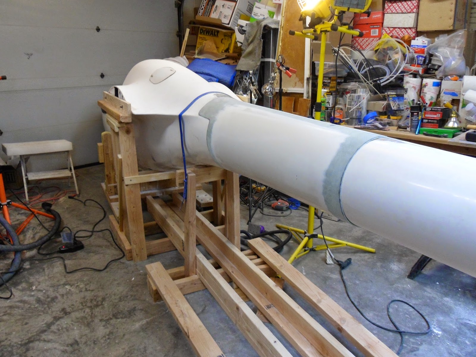
The trimming and fitting of the skin. seems to be a never ending process.

I added the support stringer on the top and bottom of the seam (per the original design), along with making the internal flanges for the skin to fit over.
 During the re-plumbing of the TE probe and static ports, I was concerned
with how the tubing was just flopping in the glass straps.
During the re-plumbing of the TE probe and static ports, I was concerned
with how the tubing was just flopping in the glass straps.

I came up with an idea to hold the tubes in place, but still giving them play to flex. I found that the semi-dense foam padding used to ship electronics would hold the tubes, and yet conform to the tubes shape without pinching.
I showed this to Robert and he found it to be a great idea, and gave me the go ahead to pad the tubing. The foam was cut to fit in the strap, and was secured using epoxy on the strap side to hold the foam in place.
I showed this to Robert and he found it to be a great idea, and gave me the go ahead to pad the tubing. The foam was cut to fit in the strap, and was secured using epoxy on the strap side to hold the foam in place.
 I also used the foam to pad the transponder coax to prevent it from chaffing.
 The tail boom is plumbed, wired, push rods in place, and ready to be buttoned up. Robert needs to inspect the work before I can proceed.
The following week, Robert stopped by to inspect the work. We was please with repair and gave me the go ahead to proceed with sealing up the fuselage.
Before attaching the side skin, I placed a piece of sheet plastic drop cloth to protect the insides from any epoxy squeeze-out and rigged the plastic with a pull cord which will enable me to remove by pulling through the open bulkheads to the landing gear bay.
Before attaching the side skin, I placed a piece of sheet plastic drop cloth to protect the insides from any epoxy squeeze-out and rigged the plastic with a pull cord which will enable me to remove by pulling through the open bulkheads to the landing gear bay.
 I prepped the inside of the skin and flanges, and used epoxy paste to glue the skin in place. In order to hold the skin to the flanges during the cure, I used clecos (per Roberts suggestion).
  With the skin epoxied in, it's time to bond the seams to the fuselage.
 The forward seam was scarfed and bonded...
 After the forward portion cured, the aft section received the same treatment.
Finally, I finished bonding the last repair seam.
 After the resin cured, I removed the support-alignment jig, and she is siting on her own tail now!
  I'm a little behind my planned schedule... but at least there is progress.
Saturday, December 27, 2014
The Tail Boom Repair - Part 2


The next step was to cut and trim the replacement right skin half and to do a test fit.
The old plastic PE tubing for the rudder cables and TE prop were also removed. I replaced the tubing with new PE tubing.

I reused the static port pressure intakes from the old skin.

 The new skin was secured in place using tape, hot glue and clamps. Inside support strips were bonded to the seam lines and epoxy flock and cab-o-sil paste was applied to the outside seam to fill any uneven voids between the skins.

I had to grind down the areas with the paste, and reinforce the internal backing to prevent a break through.

The aft seam was much easier to tackle. The scarfing process was fairly a textbook procedure.
After the scarfed areas were properly beveled. I did a final roughening of the surfaces and cleaned and prepped the outer areas before applying the glass.
 Using the PIK fiberglass lay-up schedule, I applied the replacement glass per the overlay repair instructions.
 I used a plastic tile trowel to squeegee off the excess resin.
There is a final layer of glass that I will need to apply over the repair areas, but I will hold off on that until the
repairs are complete and the fuselage is off the jig, so I can verify the
contour. 
With the new skin in place, and the resin cured, I re-installed the aft bulkhead with epoxy paste and glass strips. The bond will be better than the original which was nothing but a micro-bubble filler.


The PE tubing used for the rudder cable guides is a little
trickier to splice. There is no cement available to bond the tubing (it requires
heat to do that). I used a larger PE tube sleeve to cover the slice. I roughed
the inside of the sleeve and the outside of the spliced tubes with 50 grit
paper and the used super glue to secure it. The spliced sleeve was sealed with
shrink tubing.
 I created a transponder antenna cradle, using a mold from Robert. The location for the antenna need to be located at the top of the boom The elevator push rod was too close to the antenna if it were located at the near the underside of the boom.
Finally, I placed the antenna ground plate in to verify the clearance.
The RG400 cable was terminated and the antenna distance from the cockpit is 7 feet.
Next, I will be making the left skin and finish the fuselage boom repair.
Thursday, December 4, 2014
The Tail Boom Repair - Part 1

The time has come
to start work on repairing the fuselage.

I started to cut away the
damaged glass to determine how much of tail boom will need to be replaced.

The aft section had a split under seam to the tail wheel fairing. The pneumatic tubing and antenna COAX were also damaged.

After assessing the
damage, and cutting away the broken material, I removed the broken pushrods and
sent them to the shop for repair.

The underside of the fuselage was mostly scraped up, and
doesn’t look like any major repairs will be needed.

The top of fuselage
had some superficial cracks along the seam, which will require further investigation.

After cleaning out
the dirt and debris, I left the most complete side intact, though the glass
will need to be cut away after I get the broken plane on the assembly-alignment
jig .

A test fit of the broken boom to ensure the proper length.

The repaired pushed rods are back. The shop did a great job
repairing them.
Here is what the broken elevator pushrod looked like before,
Here is what the broken elevator pushrod looked like before,

And here they are repaired… The shorter one is the push rod for the vertical stabilizer.

Now comes the time to make the
tail boom skin mold. Robert let borrow his project PIK-20B to make the molds
from. The unfortunate thing about this plane is that all of the paint was
scraped off with a grinder, so it is uneven in spots, but for the most part
it’s useable.

My first step in making the mold was to find the center seam line. A laser
line was a good tool for that task.

Next,
tape and plastic were used to mask the mold halves.

The surface was
prepped with PVA and wax, then a layer of tooling gelcoat was applied, followed
by several layers of fiberglass, starting with a 6oz ply followed by a 10 oz, 18
oz roving and 6 oz chopped glass.

After the molds were completed, the alignment jig was
constructed. I used 2x4’s, although steel tubing would be the preferred material.

Here is the completed jig with the broken PIK secured to it.
A special note
After placing the wreck on the jig: I found out that the one I used to make the Jig was 2" longer than mine. Some where in production, they made changes to the design. And down the line, at least 38 airframes between Roberts and mine, they shortened the fuselage. This changed the boom shape slightly, and of course, it would have been in the area that was broken
I have looked at 4 PIK-20's and found changes in the design and materials used. They were not identical, which surprised me, since they were supposed to be the same model!

The first repairs were to the aft portion of the tail boom. The underside seam was split wide open. Robert recommended the use of clecos to hold the seam closed when I re-bond the surfaces. So, after cleaning and roughing up the surface, I re-bonded the seam with epoxy paste.

After the epoxy cured, I prepped the surface, filled the cleco hole with epoxy-flock paste and laid in 2 ply's of 92125 to strengthen the seam.

After the layers cured, I sanded the surface and used bondo
filler to even out the seam depression.
After sanding down the bondo to even
out the curve, a final layer of 90070 was used to strengthen the filler.

Now
the biggest step of this project, making the fuselage tail boom skins. The
mold was prepped and treated with PVA and wax, and then a thin layer of white gelcoat was applied
followed by the application of the 5 layers of glass that makes up the fuselage
skin. I used the layup scheduled provided by the manufacturer.

Finally, after 24 hours of curing, I popped the skin out of the mold, and required little cleanup.
The post cure will follow after the repairs are completed.

And the last repair was to the aft bulkhead. There was a split in the side. I anchored it to a flat surface and patched the crack with glass and flock paste.
So this concludes Part 1 on the tail boom repair.
Subscribe to:
Posts (Atom)